Free Shipping
Anywhere in the USA
W25-24 by Anchor Fluid Power | Butt Weld 4-Bolt Hydraulic Flange, Flat Face | 1-1/2" Code 61 Flange x 1-1/2" Weld End | Schedule 160 Pipe | Carbon Steel
Buy more, save moreDiscounts applied in cart/checkout.
SAE J518 Code 61
Butt Weld 4-Bolt Flanges, Schedule 40, 80 and 160
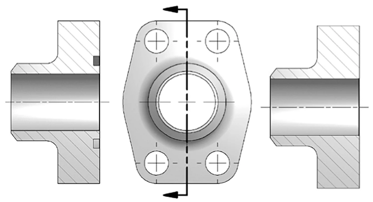
Carbon steel SAE J518 4-bolt flanges with a beveled end that is butt welded to pipe.
1
What are the key specifications?
Material
Carbon steel
Standard
SAE J518 4-bolt flange pattern
Sizes
Code 61: 3/4" to 3"
Face
O-ring groove or flat face
Mounting Kit
Suffix U: O-ring + 4 socket head cap screws
Pipe Schedules
Schedule 40, Schedule 80, Schedule 160
2
Which sizes are available?

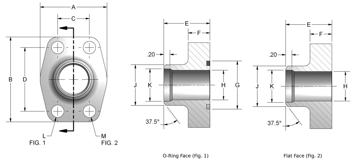
| Pipe / Pad Size | O-Ring Face | O-Ring + Kit | Flat Face | A (in) | B (in) | C (in) | D (in) | E (in) | F (in) | G (in) | H (in) | J (in) | K (in) | L (in) | M UNC-2B | Kit O-Ring | Kit Screws (4) |
|---|---|---|---|---|---|---|---|---|---|---|---|---|---|---|---|---|---|
| Code 61 Schedule 40 | |||||||||||||||||
| 3/4" | W35-12 | W35-12U | W34-12 | 1.970 | 2.560 | 0.875 | 1.875 | 1.420 | 0.710 | 1.250 | 0.744 | 1.050 | 0.846 | 0.406 | 3/8-16 | 2-214 | 3/8-16 x 1.50 |
| 1" | W35-16 | W35-16U | W34-16 | 2.170 | 2.750 | 1.031 | 2.062 | 1.500 | 0.710 | 1.560 | 0.959 | 1.315 | 1.051 | 0.406 | 3/8-16 | 2-219 | 3/8-16 x 1.50 |
| 1-1/4" | W35-20 | W35-20U | W34-20 | 2.680 | 3.120 | 1.188 | 2.312 | 1.610 | 0.830 | 1.750 | 1.280 | 1.660 | 1.382 | 0.469 | 7/16-14 | 2-222 | 7/16-14 x 1.75 |
| 1-1/2" | W35-24 | W35-24U | W34-24 | 3.070 | 3.660 | 1.406 | 2.750 | 1.730 | 0.980 | 2.115 | 1.502 | 1.900 | 1.612 | 0.531 | 1/2-13 | 2-225 | 1/2-13 x 1.75 |
| 2" | W35-32 | W35-32U | W34-32 | 3.540 | 4.000 | 1.688 | 3.062 | 1.770 | 0.980 | 2.490 | 1.941 | 2.375 | 2.069 | 0.531 | 1/2-13 | 2-228 | 1/2-13 x 1.75 |
| 2-1/2" | W35-40 | W35-40U | W34-40 | 4.090 | 4.490 | 2.000 | 3.500 | 1.970 | 0.980 | 2.995 | 2.325 | 2.875 | 2.471 | 0.531 | 1/2-13 | 2-232 | 1/2-13 x 1.75 |
| 3" | W35-48 | W35-48U | W34-48 | 4.880 | 5.280 | 2.438 | 4.188 | 1.970 | 1.060 | 3.615 | 2.902 | 3.500 | 3.070 | 0.656 | 5/8-11 | 2-237 | 5/8-11 x 2.00 |
| Code 61 Schedule 80 | |||||||||||||||||
| 3/4" | W24-12 | W24-12U | W23-12 | 1.970 | 2.560 | 0.875 | 1.875 | 1.420 | 0.710 | 1.250 | 0.744 | 1.050 | — | 0.406 | 3/8-16 | 2-214 | 3/8-16 x 1.50 |
| 1" | W24-16 | W24-16U | W23-16 | 2.170 | 2.750 | 1.031 | 2.062 | 1.500 | 0.710 | 1.560 | 0.959 | 1.315 | — | 0.406 | 3/8-16 | 2-219 | 3/8-16 x 1.50 |
| 1-1/4" | W24-20 | W24-20U | W23-20 | 2.680 | 3.120 | 1.188 | 2.312 | 1.610 | 0.830 | 1.750 | 1.280 | 1.660 | — | 0.469 | 7/16-14 | 2-222 | 7/16-14 x 1.75 |
| 1-1/2" | W24-24 | W24-24U | W23-24 | 3.070 | 3.660 | 1.406 | 2.750 | 1.730 | 0.980 | 2.115 | 1.502 | 1.900 | — | 0.531 | 1/2-13 | 2-225 | 1/2-13 x 1.75 |
| 2" | W24-32 | W24-32U | W23-32 | 3.540 | 4.000 | 1.688 | 3.062 | 1.770 | 0.980 | 2.490 | 1.941 | 2.375 | — | 0.531 | 1/2-13 | 2-228 | 1/2-13 x 1.75 |
| 2-1/2" | W24-40 | W24-40U | W23-40 | 4.090 | 4.490 | 2.000 | 3.500 | 1.970 | 0.980 | 2.995 | 2.325 | 2.875 | — | 0.531 | 1/2-13 | 2-232 | 1/2-13 x 1.75 |
| 3" | W24-48 | W24-48U | W23-48 | 4.880 | 5.280 | 2.438 | 4.188 | 1.970 | 1.060 | 3.615 | 2.902 | 3.500 | — | 0.656 | 5/8-11 | 2-237 | 5/8-11 x 2.00 |
| Code 61 Schedule 160 | |||||||||||||||||
| 3/4" | W27-12 | W27-12U | W25-12 | 1.970 | 2.560 | 0.875 | 1.875 | 1.420 | 0.710 | 1.250 | 0.614 | 1.050 | — | 0.406 | 3/8-16 | 2-214 | 3/8-16 x 1.50 |
| 1" | W27-16 | W27-16U | W25-16 | 2.170 | 2.750 | 1.031 | 2.062 | 1.500 | 0.710 | 1.560 | 0.817 | 1.315 | — | 0.406 | 3/8-16 | 2-219 | 3/8-16 x 1.50 |
| 1-1/4" | W27-20 | W27-20U | W25-20 | 2.680 | 3.120 | 1.188 | 2.132 | 1.610 | 0.830 | 1.750 | 1.162 | 1.660 | — | 0.469 | 7/16-14 | 2-222 | 7/16-14 x 1.75 |
| 1-1/2" | W27-24 | W27-24U | W25-24 | 3.070 | 3.660 | 1.406 | 2.750 | 1.730 | 0.980 | 2.115 | 1.340 | 1.900 | — | 0.531 | 1/2-13 | 2-225 | 1/2-13 x 1.75 |
| 2" | W27-32 | W27-32U | W25-32 | 3.540 | 4.000 | 1.688 | 3.062 | 1.770 | 0.980 | 2.490 | 1.689 | 2.375 | — | 0.531 | 1/2-13 | 2-228 | 1/2-13 x 1.75 |
| 2-1/2" | W27-40 | W27-40U | W25-40 | 4.090 | 4.490 | 2.000 | 3.500 | 1.970 | 0.980 | 2.995 | 2.127 | 2.875 | — | 0.531 | 1/2-13 | 2-232 | 1/2-13 x 1.75 |
| 3" | W27-48 | W27-48U | W25-48 | 4.880 | 5.280 | 2.438 | 4.188 | 1.970 | 1.060 | 3.615 | 2.626 | 3.500 | — | 0.656 | 5/8-11 | 2-237 | 5/8-11 x 2.00 |
Dimensions in inches; letters as on the drawing. O-ring face (Fig. 1) and flat face (Fig. 2) share dimensions except the O-ring groove. “+ Kit” part numbers (suffix U) include the mounting kit: 1 O-ring and 4 socket head cap screws.
3
How do I read the part number?
Example: W24-24 = Code 61 butt weld 4-bolt flange, O-ring face, 1-1/2" pad.
| Code | Meaning |
|---|---|
| Series | |
| W34 | Code 61 Schedule 40 Flat Face |
| W35 | Code 61 Schedule 40 O-Ring Face |
| W23 | Code 61 Schedule 80 Flat Face |
| W24 | Code 61 Schedule 80 O-Ring Face |
| W25 | Code 61 Schedule 160 Flat Face |
| W27 | Code 61 Schedule 160 O-Ring Face |
| Sizes | |
| Dash number | Pad (flange) size in 1/16" |
| U suffix | Mounting kit included: O-ring + 4 SHCS |
4
Where can I find product documents?
Anchor Catalog Page: Butt Weld 4-Bolt Flanges
Dimension tables by part number with mounting hardware.
Dimensions are from Anchor Fluid Power and are subject to change without notice.
How is this product sold?
Each. Part numbers ending in U include the mounting kit (1 O-ring, 4 socket head cap screws); others are the flange only.
Additional Product Data:
Shape:
Straight
Ends Configuration:
Material(s):
Specifications and Approvals: